Choosing the right wiring method is essential for the proper operation of a motorized ball valve. Different wiring types use different control logic and may be suitable for different control systems, such as switches, relays, PLCs, and other automation equipment.
In this guide, we introduce five common wiring and control options for Flomarvel motorized ball valves — OP01, OP02, OP03, OP04, and OP05 — to help you understand their differences and select the right option for your application.
OP01 - Reverse Polarity Control
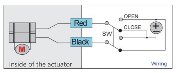
Connects red wire to positive pole, black wire to negative pole, the ball valve opens.
Reverse polarity, the ball valve closes.
※ Once in position, there will be no power consumption.
※ In case of power loss, valve will remain in its current state.
※ Voltage of power supply for option:5V DC/12V DC/9-35V DC
※ A DPDT switch is suggested for a simple set up.
OP02 - 3-Wire Open/Close Control
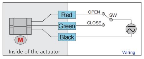
1. Connects red wire to positive pole, black wire to negative pole, the ball valve opens.
2. Connects green wire to positive pole, black wire to negative pole, the ball valve closes.
※ Once in position, there will be a very low standby power consumption.
※ In case of power loss, valve will remain in its current state.
※ Voltage of power supply for option:5V DC/9-35V DC/85V-220V AC
※ A SPDT switch is suggested for a simple set up.
OP03 – Power On/Open, Power Off/Close
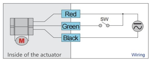
1. Connects red wire and green wire to positive pole, black wire to negative pole, the ball valve opens.
2. Disconnects green wire, the ball valve closes.
※ Once in position, there will be a very low standby power consumption..
※ In case of power loss, valve will remain in its current state.
※ Voltage of power supply for option:5V DC/9-24V ADC/85-220V AC
※ A on/off switch can be installed in line with green wire for a simple set up.
OP04 – Fail-Safe Auto-Return Control
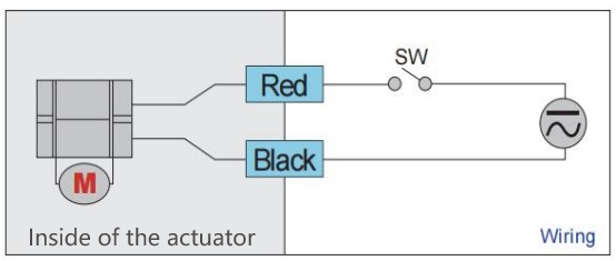
1. Connects red wire to positive pole, black wire to negative pole, the ball valve opens (the ball valve is normally closed by default).
2. Disconnect either wire (the circuit is open), there is no power supply to the ball valve, the ball valve closes.
※ Once in position, there is a nominal power consumption to keep the capacitor charged.
※ In case of power loss, valve will return to its normal position, which is closed by default. If normally open ball valve is needed, please let us know when place an order.
※ Voltage of power supply for option:5V DC/9-24V ADC/85-230V AC
※ A on/off switch can be installed in line with red wire for a simple set up.
OP05 – External Signal Control
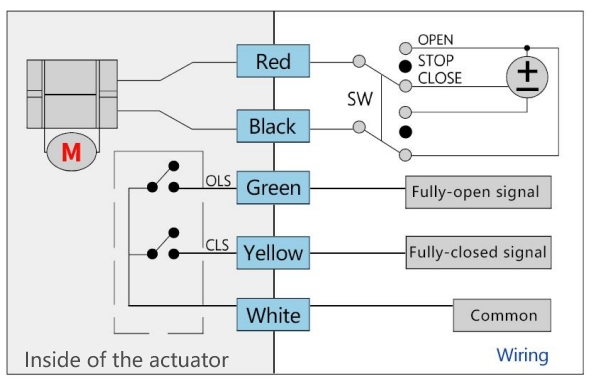
1. Connects red wire to positive pole, black wire to negative pole, the ball valve keeps rotating counterclockwise; reverse polarity, the ball valve keeps rotating clockwise.
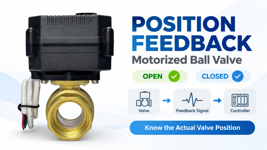
2. When the fully open or fully closed position is reached, position signals are sent to external equipment through the signal wires.
3. External equipment sends an OPEN/CLOSE/STOP command to valve through the signal wires according the position signal received.
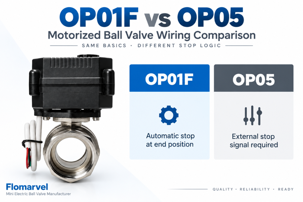
This means that OP05 relies completely on external control logic. Even if the limit switches have detected the end position and feedback signals have already been transmitted, the actuator itself does not automatically stop or disconnect power.
If external equipment continues supplying power and does not remove the control signal, the motor may continue running.
Key Characteristics of OP05·
● Requires external OPEN/CLOSE/STOP control commands.
● Requires external equipment to monitor feedback signals.
● Requires external equipment to cut off power after receiving position feedback.
● The actuator itself does not perform automatic power-off control.
※ Once in position, there will be no power consumption.
※ In case of power loss, valve will remain in its current state.
※ Voltage of power supply for option:5V DC/12V DC/24V DC
※ A DPDT switch is suggested for a simple set up.
The main difference between OP05 and OP01–OP04 is that the actuator does not rely solely on its internal limit control to complete the opening and closing operation. Instead, it requires an external control system to provide the corresponding control and stop signals.
For example, when connected to a PLC, controller, or relay system, the external system sends a control signal to operate the actuator. Once the required position or condition is reached, an external signal is used to stop the actuator. Therefore, OP05 is more suitable for applications where the control logic is managed by an external control system.